 Placing distributors
|
Tool |
Tool set |
|
Distributor
|
Lighting |
The Electrical Component tool and the Distributor tool share the same position in the Lighting tool set. Click and hold the mouse on the visible tool to open the Pop-out tools list and select the desired tool.
The Distributor tool places power distribution objects such as power distribution racks, dimmer racks, breakout boxes, twofers, and so on. Distributor objects split power or signals to the cables. A large variety of distributor resources are available in the Vectorworks libraries; navigate to [User]\Libraries\Defaults\Cable Tools to browse the default content. To create a custom distributor symbol with any number of inputs, outputs, and fuses, see Creating custom electrical devices.
A distributor object is considered a load, and can be included in load calculations (Braceworks required). Distributors can be labeled with data tag objects; see Using data tags.
![]()
|
Mode |
Description |
|
Distributor Symbol |
Opens the Resource Selector to select a distributor resource for placement; double-click a resource to activate it |
|
Automatic Numbering
|
Enables automatic numbering of distributors as they are placed |
|
Numbering Preferences
|
Set the default parameters for automatic numbering of distributors |
To insert a distributor:
Click the tool. From the Tool bar, enable Automatic Numbering if desired, and specify the Numbering Preferences. See Automatic numbering preferences.
Click Distributor Symbol on the Tool bar to select a resource from the Resource Selector.
If you do not select a distributor resource, a rectangle is placed.
Click to place the distributor in the drawing. The object can be attached to a rigging object; see Concept: Attaching loads to rigging objects.
The parameters can be edited later from the Object Info palette.
Click to show/hide the parameters.Click to show/hide the parameters.
|
Parameter |
Description |
|
General |
|
|
ID |
Provide a unique identifier for labels, power patching, and paperwork. If blank, a value is automatically assigned when calculations are run (Braceworks required). |
|
Name |
Displays the name of the distributor model for paperwork; the name can be changed |
|
Location |
Enter the name of the associated rigging object or other location information for paperwork |
|
Classes |
Opens the Classes dialog box, to specify class naming for the distributor label and length indicators. This allows them to be set to visible, grayed, or invisible. Use the standard class, select a class from the list of classes present in the drawing, or create a new class. Select <Object Class> to place the label or indicators in the same class as the distributor. Use Standard Classes: Specifies an optional default root class naming standard for the label and indicator; all label and indicator class names begin with the prefix, so that they are sorted together. Label: Specifies the class to use for the distributor label. Output length indicators: Specifies the class to use for the output length indicator. |
|
Symbol |
Displays the name of the symbol used to represent the distributor |
|
Select Symbol |
Opens a Resource Selector to select a different distributor symbol; double-click a resource to activate it |
|
Connections |
|
|
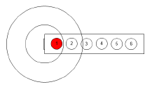
Draw output lengths |
Draws the Connector Length using circles as an indicator to represent the maximum length |
|
Load Information |
A distributor is considered a point load in Braceworks calculations; if the insertion point is on a structural element, it is considered to be a load on that structure. Load information is used for Braceworks calculations and reports (Braceworks required). |
|
Include in calculations (Braceworks required) |
Includes the distributor in Braceworks calculations; deselect to exclude the object from participating in structural calculations |
|
Load Group Name |
The load category is always Cable for distributors |
|
Load ID |
Enter a unique ID for the load for informational use in reports |
|
Load Name |
Identifies the object in load calculations; normally the object name is used |
|
Total Weight |
Enter the total weight of the object |
|
Position |
Displays the name of the associated rigging object, if the distributor is attached. Optionally, attach this object to a rigging object, or change the rigging object association, by entering the Position Name of the rigging object. Delete the name to break the association. For other methods to attach loads, see Making the attachment. |
|
Power Information |
A distributor can be power patched within the electrical system; see Power patching from the Object Info palette. Power information is used for power calculations and reports. Different parameters display for different types of distributor objects. |
|
Select Range |
The socket connection parameters are displayed in sets of seven. Select which set of sockets to display for editing. The sets are numbered according to the input/output stacking order. |
|
Power source parameters (power source distributors only) |
Output: Select the socket for the output connection Max Payload: Displays the maximum electrical load the power source can handle Voltage: Displays the voltage per phase of the power source Connector: Displays the connector used by the power source |
|
Input parameters (plugbox or breakout distributors only) |
Input: Select the socket for the input connection Voltage: Displays the voltage from the input connection Connector: Displays the connector for the input connection Power Source: Displays the power source for the distributor |
|
Select Power Source |
Click to select a power source for the distributor |
|
Output parameters (plugbox or breakout distributors only) |
Output: Select the socket for each output connection Voltage: Displays the voltage from the output connection Connector: Displays the connector for the output connection |
When a distributor is moved, the attached cables adjust to maintain the connection.
